This page guides you through soldering a 4-in-a-row kit's main board, step by step.
These steps are my recommendation, but feel free to deviate of a certain order is easier for you!
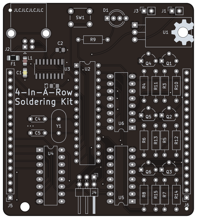
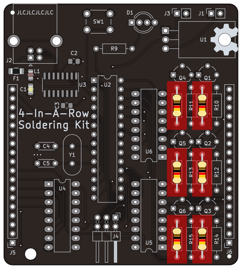
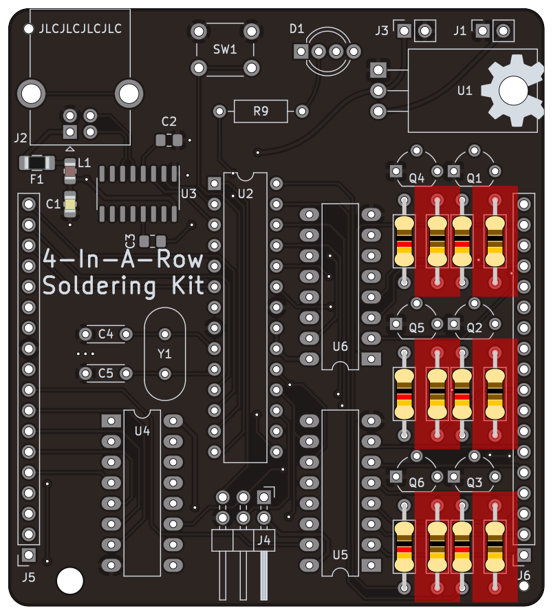
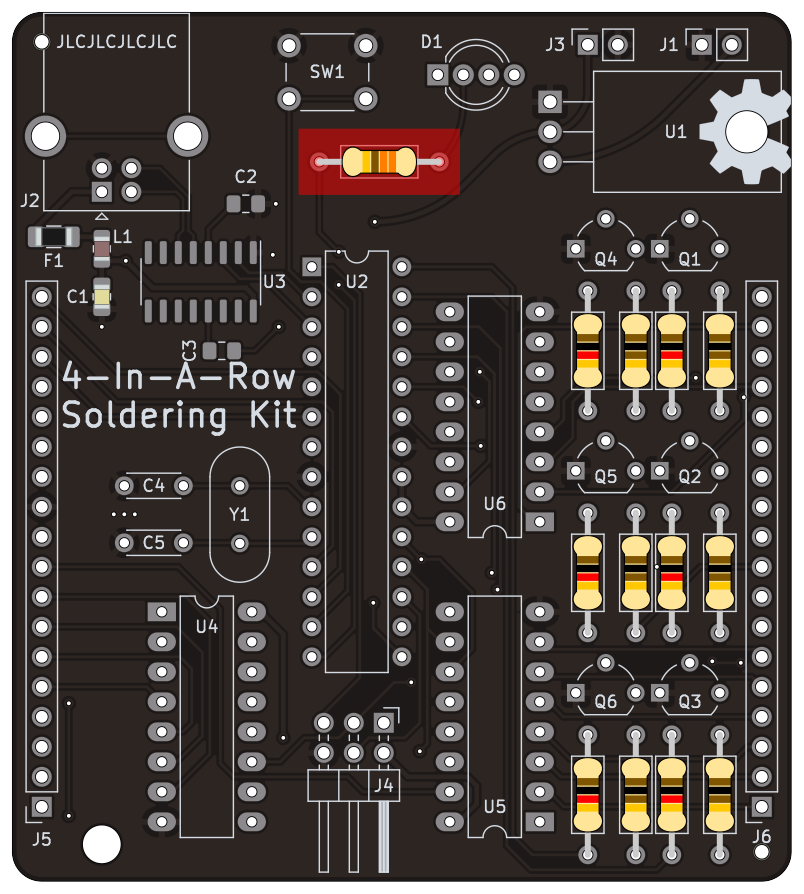
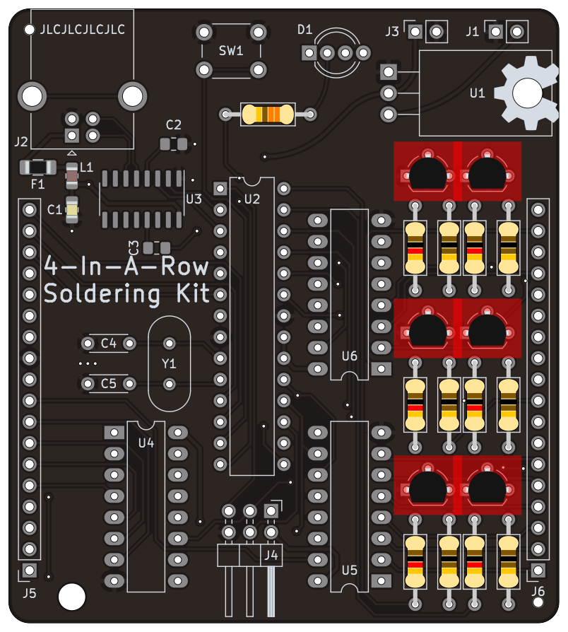
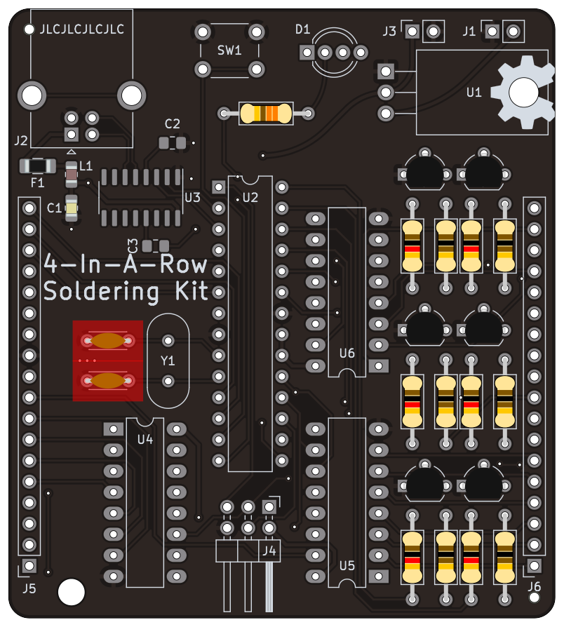
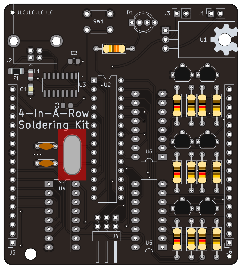
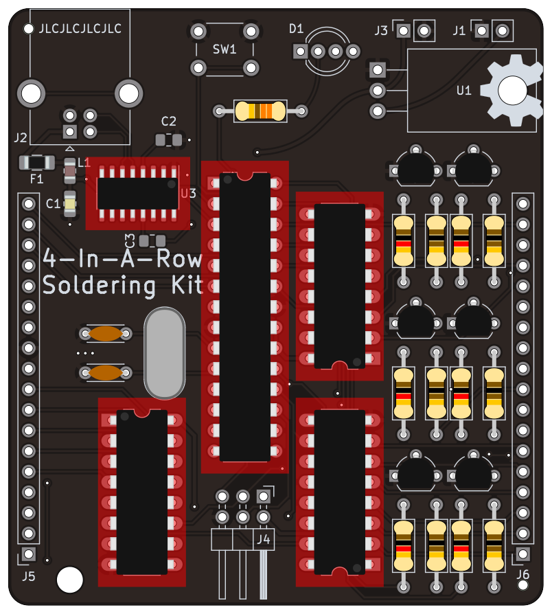
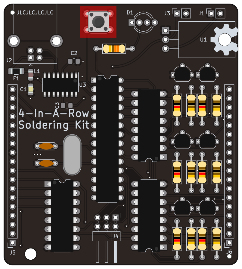
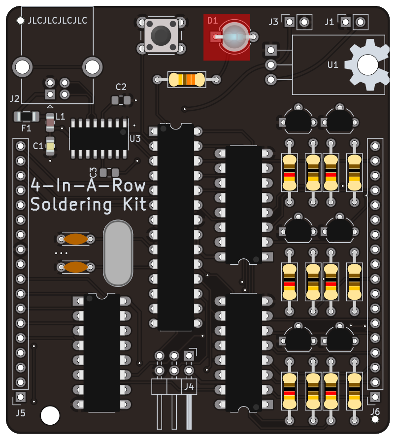
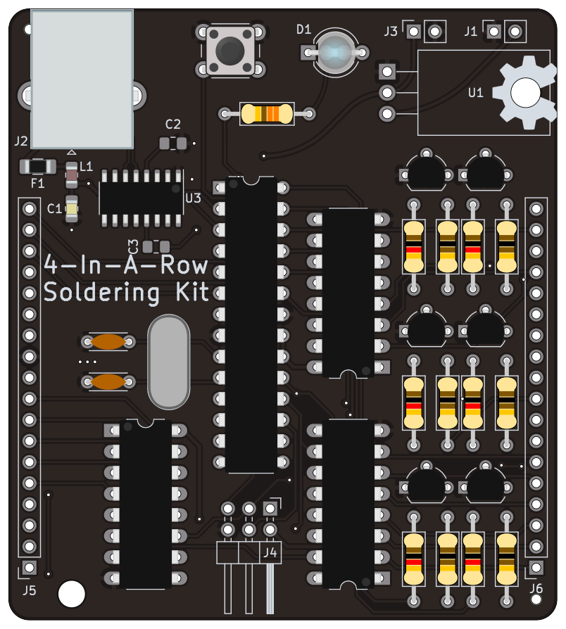
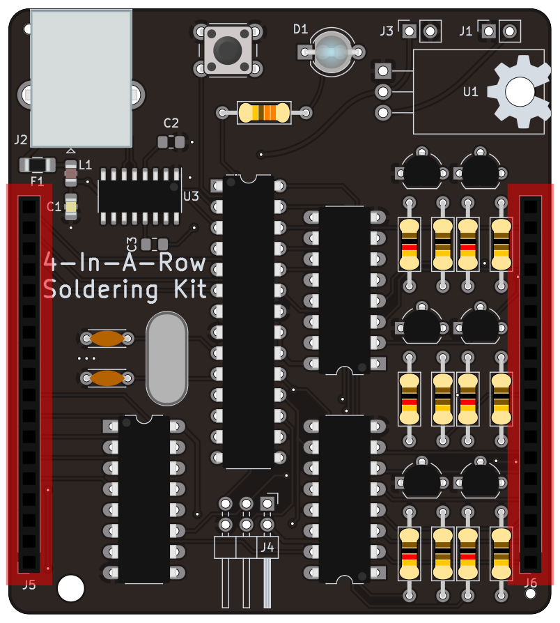
We get the empty board I recommend to solder all resistors first, as they are the thinest component and thus you can lay the board down with the resistors populated while soldering. I started with 1kΩ resistors, but you can choose any order Then we solder the next set of resistor values, which are 100Ω Then we populate all 2N3904 transistors We populate the 12pF capacitors for the crystal And then the crystal itself Then we populate the ICs. In this drawing, the ICs are directly shown. THIS IS NOT RECOMMENDED. Instead, use the pin headers, and then push the component into them. Then we populate the switch And the main indicator diode The USB connector Then finally, the side pin sockets that will interconnect to the main board OPTIONALLY, solder U1 if you intend to use an external 7-12v source (such as a 9v battery)